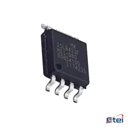
Hình ảnh chỉ để tham khảo
74HC574PW
+BOMFlip Flops OCTAL D-TYPE POS EDGE 3-S
-
Nhà sản xuấtNexperia
-
Ông. Phần #74HC574PW
-
Có sẵn21734
365 Đảm bảo chất lượng ngày
7*24 giờ dịch vụ quarantee
90-Bảo hành sau bán hàng ngày
Bảo hành sản phẩm chính xác
Thông số kỹ thuật
| thuộc tính | Giá trị |
| StandardPackQty | 75 |
Tổng quan
Description
The 74HC574PW is a high-speed CMOS octal D-type flip-flop with 3-state outputs, commonly used in digital electronics. It features eight edge-triggered D-type flip-flops with individual data inputs (D0 to D7) and a common clock (CP) and output enable (OE) input. The device is designed to improve the performance and density of digital systems, making it suitable for a variety of applications such as data storage, data latching, and timing signal synchronization.
Key features include a supply voltage range of 2V to 6V, low power consumption, and the ability to drive up to 10 LSTTL loads. The 74HC574PW is part of the 74HC family, characterized by fast switching times and balanced propagation delays. The three-state outputs can be directly connected to a bus, allowing for efficient data communication between components.
The device is typically housed in a TSSOP-20 package, making it compact and easy to integrate into various electronic designs. It is ideal for applications requiring high-speed data capture and temporary data storage.
Key features include a supply voltage range of 2V to 6V, low power consumption, and the ability to drive up to 10 LSTTL loads. The 74HC574PW is part of the 74HC family, characterized by fast switching times and balanced propagation delays. The three-state outputs can be directly connected to a bus, allowing for efficient data communication between components.
The device is typically housed in a TSSOP-20 package, making it compact and easy to integrate into various electronic designs. It is ideal for applications requiring high-speed data capture and temporary data storage.
Equivalent
The 74HC574PW is a high-speed CMOS Octal D-type flip-flop with 3-state outputs. Equivalent products include:
1. SN74HC574N (Texas Instruments)
2. MC74HC574ADWG (ON Semiconductor)
3. CD74HC574E (Texas Instruments)
4. TC74HC574AP (Toshiba)
5. HEF4754B (NXP)
These parts are similar in function and can often be used interchangeably, but always check the specific datasheets for compatibility.
1. SN74HC574N (Texas Instruments)
2. MC74HC574ADWG (ON Semiconductor)
3. CD74HC574E (Texas Instruments)
4. TC74HC574AP (Toshiba)
5. HEF4754B (NXP)
These parts are similar in function and can often be used interchangeably, but always check the specific datasheets for compatibility.
Features
The 74HC574PW is a high-speed Si-gate CMOS device featuring an octal D-type flip-flop with 3-state outputs. It operates at a supply voltage range of 2V to 6V, suitable for a variety of applications. Key features include:
1. High-Speed Operation: Designed for fast data processing.
2. 3-State Outputs: Each flip-flop output can be set to high, low, or high-impedance state, allowing for easy data bus interfacing.
3. Latch Capability: Data is stored upon a low-to-high transition of the clock input.
4. Output Capability: Standard outputs can drive up to 10 LSTTL loads.
5. Pin Count and Package: Available in a TSSOP20 package for space-saving designs.
6. Operating Temperature Range: Typically from -40°C to +125°C, making it suitable for industrial applications.
7. Low Power Consumption: CMOS technology ensures reduced power usage.
These features make the 74HC574PW ideal for use in digital systems requiring controlled data storage and retrieval, such as microcontroller interfacing and memory management.
1. High-Speed Operation: Designed for fast data processing.
2. 3-State Outputs: Each flip-flop output can be set to high, low, or high-impedance state, allowing for easy data bus interfacing.
3. Latch Capability: Data is stored upon a low-to-high transition of the clock input.
4. Output Capability: Standard outputs can drive up to 10 LSTTL loads.
5. Pin Count and Package: Available in a TSSOP20 package for space-saving designs.
6. Operating Temperature Range: Typically from -40°C to +125°C, making it suitable for industrial applications.
7. Low Power Consumption: CMOS technology ensures reduced power usage.
These features make the 74HC574PW ideal for use in digital systems requiring controlled data storage and retrieval, such as microcontroller interfacing and memory management.
Pinout
The 74HC574PW is a high-speed CMOS device from the 74HC series, commonly used as an octal D-type flip-flop with 3-state outputs. It comes in a TSSOP (Thin Shrink Small Outline Package) with 20 pins.
Here is a brief description of its pin configuration and functions:
1. VCC (Pin 20): Power supply pin.
2. GND (Pin 10): Ground pin.
3. Q0 to Q7 (Pins 2, 3, 4, 5, 6, 7, 8, 9): Parallel outputs corresponding to the D-type flip-flops.
4. D0 to D7 (Pins 3, 4, 5, 6, 7, 8, 9, 11): Data inputs for each flip-flop.
5. OE (Pin 1): Output enable pin; active low. When low, the outputs are enabled; when high, the outputs are in high-impedance state.
6. CP (Pin 11): Clock pulse input; data is latched on the rising edge of the clock pulse.
The device is typically used in digital systems for temporary data storage and data synchronization tasks, leveraging its ability to capture and retain digital data at high speeds.
Here is a brief description of its pin configuration and functions:
1. VCC (Pin 20): Power supply pin.
2. GND (Pin 10): Ground pin.
3. Q0 to Q7 (Pins 2, 3, 4, 5, 6, 7, 8, 9): Parallel outputs corresponding to the D-type flip-flops.
4. D0 to D7 (Pins 3, 4, 5, 6, 7, 8, 9, 11): Data inputs for each flip-flop.
5. OE (Pin 1): Output enable pin; active low. When low, the outputs are enabled; when high, the outputs are in high-impedance state.
6. CP (Pin 11): Clock pulse input; data is latched on the rising edge of the clock pulse.
The device is typically used in digital systems for temporary data storage and data synchronization tasks, leveraging its ability to capture and retain digital data at high speeds.
Manufacturer
The 74HC574PW is manufactured by Nexperia. Nexperia is a global semiconductor company that specializes in the production of discrete components, logic devices, and MOSFETs. Originally part of NXP Semiconductors, Nexperia became an independent company in 2017. It focuses on efficiency and reliability in its product offerings, catering to the automotive, industrial, computing, and consumer electronics markets. The company is known for its robust supply chain and manufacturing capabilities, emphasizing high-volume production and quality control.
Application
The 74HC574PW is an octal D-type flip-flop with 3-state outputs, commonly used in digital electronics. Its primary application areas include data storage and transfer, where it temporarily holds and manages data. It is often utilized in microcontroller interfacing, buffering signals, and managing data flow between different parts of a system. Additionally, it can be used in digital signal processing, memory management units, and as a latch in various digital circuits. The device is suitable for use in computing, communication systems, and other embedded systems requiring efficient data handling and state retention.
Package
The 74HC574PW is a high-speed CMOS octal D-type flip-flop with 3-state outputs. It comes in a TSSOP (Thin Shrink Small Outline Package) with 20 pins, suitable for surface-mount technology.