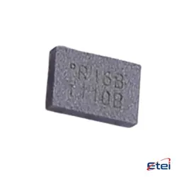
Hình ảnh chỉ để tham khảo
BGU6104,147
+BOMIC RF AMP GP 40MHZ-4GHZ 6HXSON
-
Nhà sản xuấtNXP Hoa Kỳ Inc.
-
Ông. Phần #BGU6104,147
-
Bảng dữ liệu BGU6104,147 DataSheet
-
Có sẵn2653
365 Đảm bảo chất lượng ngày
7*24 giờ dịch vụ quarantee
90-Bảo hành sau bán hàng ngày
Bảo hành sản phẩm chính xác
Thông số kỹ thuật
| thuộc tính | Giá trị |
| Supplier | NXP USA Inc. |
| Package | Tape & Reel (TR),Cut Tape (CT) |
| ProductStatus | Active |
| Frequency | 40MHz ~ 4GHz |
| P1dB | 13dBm |
| Gain | 16.5dB |
| NoiseFigure | 2.2dB |
| RFType | General Purpose |
| Voltage-Supply | 1.5V ~ 5V |
| Current-Supply | 40mA |
| TestFrequency | 3.5GHz |
| MountingType | Surface Mount |
| Package/Case | 6-XFDFN Exposed Pad |
Tổng quan
Description
The introduction might cover:
1. Course Objectives: What the course aims to achieve, including the learning outcomes expected by the end of the module.
2. Curriculum Overview: A brief outline of the main topics and themes that will be covered throughout the course.
3. Assessment Methods: Information on how students will be evaluated, such as exams, assignments, or projects.
4. Key Resources: Recommended textbooks, articles, and other resources essential for the course.
5. Instructor Information: Details about the instructor, including contact information and office hours.
6. Schedule: Important dates for lectures, assignments, and exams.
To get a more detailed and specific introduction, consulting the course syllabus or contacting the academic institution directly would be ideal.
Equivalent
1. Analog Devices: HMC374SC70
2. Qorvo: QPL9547
3. Skyworks: SKY67151-396LF
It’s essential to compare specific parameters like gain, noise figure, frequency range, and power supply to ensure compatibility with your application.
Pinout
1. RF_IN: This is the RF input pin where the GPS signal is fed into the amplifier.
2. VCC: Power supply pin for the device.
3. RF_OUT: The amplified RF output signal is available at this pin.
4. VBIAS: This pin is used to set the bias current or voltage for optimal performance.
5. GND: Ground pin for electrical grounding.
6. Enable/Disable: A control pin to enable or disable the amplifier's operation.
These pins collectively ensure the module's effective functionality as a low-noise amplifier, enhancing weak satellite signals for improved GPS accuracy. Always refer to the specific datasheet for precise pin configuration and usage details.