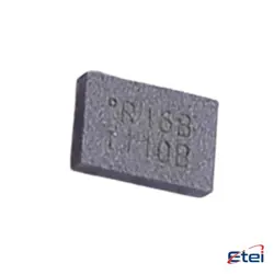
Hình ảnh chỉ để tham khảo
HMC440QS16GE
+BOMIC RF DETECT 10MHZ-2.8GHZ 16QSOP
-
Nhà sản xuấtCông ty Analog Devices Inc.
-
Ông. Phần #HMC440QS16GE
-
Bảng dữ liệu HMC440QS16GE DataSheet
-
Gói QSOP-16
-
Có sẵn3772
365 Đảm bảo chất lượng ngày
7*24 giờ dịch vụ quarantee
90-Bảo hành sau bán hàng ngày
Bảo hành sản phẩm chính xác
Thông số kỹ thuật
| thuộc tính | Giá trị |
| Package / Case | Strip |
| Part Status | Active |
| Frequency | 10MHz ~ 2.8GHz |
| RF Type | General Purpose |
| Input Range | -10dBm ~ 10dBm |
| Voltage - Supply | 4.8V ~ 5.2V |
| Supply Current | 250 mA |
| Mounting Type | Surface Mount |
Tổng quan
Description
Key features include low phase noise, which is critical for maintaining signal integrity, and a wide frequency range that allows for versatility in different applications. The HMC440QS16GE is housed in a compact QSOP-16 package, facilitating easy integration into various circuit designs. It generally operates over a broad temperature range, making it suitable for both commercial and industrial environments.
The device supports various power supply options and typically comes with a programmable divider, which offers flexibility in output frequency selection. Additionally, it often includes advanced features for reducing spurious signals, enhancing overall system performance.
Equivalent
Features
The HMC440QS16GE is housed in a 16-lead QSOP package, making it compact and suitable for space-constrained designs. It operates with a low power consumption, enhancing efficiency in power-sensitive applications. The device's robust design ensures reliable performance across various environmental conditions, making it ideal for demanding RF and microwave applications. Its integration into synthesizers aids in achieving fast lock times and minimal jitter, essential for high-quality signal generation and processing.
Pinout
1. Vcc: Supply voltage for the device.
2. GND: Ground connections.
3. Charge Pump Output (CPOUT): Used to drive an external loop filter.
4. Feedback (N Divider): Connects to the output frequency for feedback.
5. Reference Input (R Divider): Connects to a stable reference frequency.
6. Data (Serial Data Input): Serial data input for programming the internal registers.
7. Clock (Serial Clock Input): Clock input for serial data programming.
8. LE (Latch Enable): Latch enable input for updating the internal register.
9. Output (RFOUT): Frequency output of the synthesized signal.
The remaining pins are typically used for additional control and configuration purposes, such as enabling or disabling certain functions or setting specific operational modes. For detailed pin descriptions and functionalities, referring to the manufacturer's datasheet is recommended.