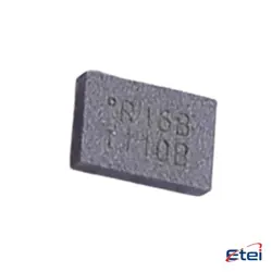
Hình ảnh chỉ để tham khảo
HMC544AETR
+BOMIC RF SWITCH SPDT 4GHZ SOT26
-
Nhà sản xuấtCông ty Analog Devices Inc.
-
Ông. Phần #HMC544AETR
-
Bảng dữ liệu HMC544AETR DataSheet
-
Gói SOT-23-6
-
Có sẵn2049
365 Đảm bảo chất lượng ngày
7*24 giờ dịch vụ quarantee
90-Bảo hành sau bán hàng ngày
Bảo hành sản phẩm chính xác
Thông số kỹ thuật
| thuộc tính | Giá trị |
| Package | Tape & Reel (TR),Cut Tape (CT) |
| ProductStatus | Active |
| RFType | WiMax, WLAN |
| Circuit | SPDT |
| FrequencyRange | 0Hz ~ 4GHz |
| Isolation | 12dB |
| InsertionLoss | 0.7dB |
| TestFrequency | 4GHz |
| P1dB | 39dBm |
| IIP3 | 60dBm |
| Impedance | 50Ohm |
| Voltage-Supply | 5V |
| OperatingTemperature | -40°C ~ 85°C |
| Package/Case | SOT-23-6 |
Tổng quan
Description
Key specifications of the HMC544AETR include a wide frequency range, typically from DC to 8 GHz, low insertion loss, high isolation, and fast switching speed. The switch operates on a single positive supply voltage and is packaged in a compact 6-lead SOT-26 package, making it suitable for space-constrained designs. Its robustness and efficiency make it a popular choice for engineers looking to design high-frequency RF systems that require reliable signal routing with minimal signal degradation.
Equivalent
1. Skyworks Solutions AS179-92LF: A similar SPDT switch with comparable RF performance.
2. Peregrine Semiconductor PE42420: Offers similar functionality and frequency range.
3. Mini-Circuits TSW-2-46+: Another SPDT switch option with similar specs.
Ensure to verify the electrical specifications and pin compatibility when considering replacements.
Features
1. Low Insertion Loss: The switch offers low insertion loss, typically around 0.9 dB to 1.3 dB, ensuring minimal signal degradation.
2. High Isolation: It provides high isolation between ports, typically around 23 dB to 35 dB, which is crucial for minimizing interference in multi-path systems.
3. High Linearity: The switch maintains high linearity with an IP3 (third-order intercept point) of about 47 dBm, making it suitable for high-performance systems.
4. Compact Package: It comes in a small 16-lead 3x3 mm QFN surface-mount package, allowing for efficient use of PCB space.
5. Control Voltage: The HMC544AETR operates with a control voltage range of 0 to +3V/+5V.
These features make the HMC544AETR suitable for use in applications such as wireless infrastructure, test and measurement equipment, and other RF systems requiring reliable and efficient switching.
Pinout
1. RFC: Common RF port.
2. RF1: Output port 1.
3. RF2: Output port 2.
4. V1: Control voltage input 1.
5. V2: Control voltage input 2.
6. GND: Ground connection.
The HMC544AETR operates by applying control voltages to the V1 and V2 pins to switch the signal path between the RFC and either RF1 or RF2. This switch is typically used for RF applications, and it offers low insertion loss and high isolation. The device is suitable for various applications, including wireless infrastructure, test equipment, and other RF systems.
Manufacturer
Application
1. Wireless Infrastructure: Used in base stations and repeaters for signal routing.
2. Test and Measurement Equipment: Facilitates signal switching in RF testing environments.
3. Military and Aerospace: Supports communication systems with its resilience and wide frequency range.
4. Microwave Radio Systems: Aids in routing signals in microwave communication.
5. Telecommunications: Utilized in infrastructure for routing RF signals.
6. Satcom (Satellite Communication): Supports satellite communication systems due to its high performance at microwave frequencies.
These diverse applications leverage its low insertion loss, high isolation, and wide bandwidth capabilities.