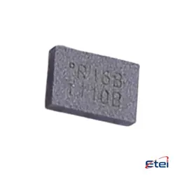
Hình ảnh chỉ để tham khảo
HMC5843
+BOM-
Nhà sản xuấtJLCPCB Assembly
-
Ông. Phần #HMC5843
-
Có sẵn7203
365 Đảm bảo chất lượng ngày
7*24 giờ dịch vụ quarantee
90-Bảo hành sau bán hàng ngày
Bảo hành sản phẩm chính xác
Thông số kỹ thuật
| thuộc tính | Giá trị |
| Manufacturer | JLCPCB Assembly |
| Package / Case | LPCC-20_L4.0-W4.0-P0.50 |
Tổng quan
Description
The HMC5843 is a three-axis digital magnetometer designed for high-precision magnetic field measurements. It is widely used in applications such as compasses, navigation systems, and motion sensing. The device operates using a low-power, integrated Hall-effect sensor and provides digital output via a serial interface (I²C or SPI), making it easy to interface with microcontrollers and other digital devices.
Key features include a programmable data rate, configurable measurement ranges, and built-in temperature compensation, which ensures accurate readings across various conditions. The HMC5843 can measure magnetic fields in the X, Y, and Z axes, allowing for comprehensive orientation and heading determination.
Due to its compact size, low power consumption, and high accuracy, the HMC5843 is ideal for portable devices, robotics, and automotive applications. It's critical to properly calibrate the sensor to account for magnetic interference and ensure reliable performance in real-world scenarios.
Key features include a programmable data rate, configurable measurement ranges, and built-in temperature compensation, which ensures accurate readings across various conditions. The HMC5843 can measure magnetic fields in the X, Y, and Z axes, allowing for comprehensive orientation and heading determination.
Due to its compact size, low power consumption, and high accuracy, the HMC5843 is ideal for portable devices, robotics, and automotive applications. It's critical to properly calibrate the sensor to account for magnetic interference and ensure reliable performance in real-world scenarios.
Equivalent
Equivalent products to the HMC5843 chip, a 3-axis digital compass, include the Honeywell HMC5883L, STMicroelectronics LSM303D (which includes a magnetometer), and the NXP FXOS8700C (which combines accelerometer and magnetometer functions). Additionally, the AKM AK8975 and the Bosch BMM150 are alternatives for magnetometer applications. Be sure to check specifications for compatibility with your project.
Features
The HMC5843 is a three-axis digital magnetometer designed for accurate magnetic field measurement. Key features include:
1. Three-Axis Measurement: It measures magnetic fields in the X, Y, and Z directions, allowing for comprehensive orientation detection.
2. Digital Output: Communicates via I²C or SPI interface, simplifying integration with microcontrollers and processors.
3. High Sensitivity: Provides high-resolution measurements, making it suitable for precise applications such as navigation and orientation sensing.
4. Low Power Consumption: Designed for battery-operated devices, it operates efficiently with minimal power draw.
5. Calibration Capability: Supports user calibration to enhance accuracy and reduce distortion from nearby objects.
6. Wide Operating Range: Functions effectively within a range of temperatures and magnetic fields.
7. Built-in Self-Test: Ensures reliability by enabling users to verify the device's functionality before deployment.
The HMC5843 is commonly used in smartphones, drones, and robotics for navigation, tilt sensing, and augmented reality applications.
1. Three-Axis Measurement: It measures magnetic fields in the X, Y, and Z directions, allowing for comprehensive orientation detection.
2. Digital Output: Communicates via I²C or SPI interface, simplifying integration with microcontrollers and processors.
3. High Sensitivity: Provides high-resolution measurements, making it suitable for precise applications such as navigation and orientation sensing.
4. Low Power Consumption: Designed for battery-operated devices, it operates efficiently with minimal power draw.
5. Calibration Capability: Supports user calibration to enhance accuracy and reduce distortion from nearby objects.
6. Wide Operating Range: Functions effectively within a range of temperatures and magnetic fields.
7. Built-in Self-Test: Ensures reliability by enabling users to verify the device's functionality before deployment.
The HMC5843 is commonly used in smartphones, drones, and robotics for navigation, tilt sensing, and augmented reality applications.
Pinout
The HMC5843 is a three-axis magnetometer with a pin count of 16. Its primary function is to measure magnetic fields in three dimensions, typically used for navigation and orientation applications.
### Pin Functions:
1. VDD (Pin 1): Supply voltage (2.2V to 3.6V).
2. GND (Pin 2): Ground reference.
3. SCL (Pin 3): Serial clock input for I²C communication.
4. SDA (Pin 4): Serial data input/output for I²C communication.
5. CS (Pin 5): Chip select (active low).
6. DRDY (Pin 6): Data ready output (indicates new data is available).
7. XOUT (Pin 7): X-axis output (analog).
8. YOUT (Pin 8): Y-axis output (analog).
9. ZOUT (Pin 9): Z-axis output (analog).
10. RESET (Pin 10): Reset input.
11. VIO (Pin 11): I/O voltage reference.
12. VREF (Pin 12): Reference voltage.
13. VDDIO (Pin 13): I/O supply voltage.
14. NC (Pins 14-16): No connect (not used).
This device is widely used in portable electronics for compass applications.
### Pin Functions:
1. VDD (Pin 1): Supply voltage (2.2V to 3.6V).
2. GND (Pin 2): Ground reference.
3. SCL (Pin 3): Serial clock input for I²C communication.
4. SDA (Pin 4): Serial data input/output for I²C communication.
5. CS (Pin 5): Chip select (active low).
6. DRDY (Pin 6): Data ready output (indicates new data is available).
7. XOUT (Pin 7): X-axis output (analog).
8. YOUT (Pin 8): Y-axis output (analog).
9. ZOUT (Pin 9): Z-axis output (analog).
10. RESET (Pin 10): Reset input.
11. VIO (Pin 11): I/O voltage reference.
12. VREF (Pin 12): Reference voltage.
13. VDDIO (Pin 13): I/O supply voltage.
14. NC (Pins 14-16): No connect (not used).
This device is widely used in portable electronics for compass applications.
Manufacturer
The HMC5843 is manufactured by Honeywell, a multinational company known for its diversified technology and manufacturing. Honeywell operates across various sectors, including aerospace, building technologies, performance materials, and safety and productivity solutions. The HMC5843 is a three-axis magnetometer, commonly used in applications such as navigation, robotics, and consumer electronics, due to its precision and reliability in measuring magnetic fields. Honeywell has a strong focus on innovation and engineering solutions, making it a key player in the technology and manufacturing industries.
Application
The HMC5843 is a three-axis digital magnetometer primarily used in various applications, including:
1. Navigation Systems: Enhancing GPS with magnetic heading information for improved accuracy.
2. Robotics: Assisting in orientation and navigation tasks for autonomous robots.
3. Aerospace: Providing attitude and heading reference for aircraft and drones.
4. Smartphones and Wearables: Enabling compass functionality and spatial orientation in mobile devices.
5. Geophysical Surveys: Measuring magnetic field variations for geological studies.
6. Virtual Reality (VR): Enhancing motion tracking for immersive experiences.
Its compact design and digital output make it suitable for integration in various electronic systems.
1. Navigation Systems: Enhancing GPS with magnetic heading information for improved accuracy.
2. Robotics: Assisting in orientation and navigation tasks for autonomous robots.
3. Aerospace: Providing attitude and heading reference for aircraft and drones.
4. Smartphones and Wearables: Enabling compass functionality and spatial orientation in mobile devices.
5. Geophysical Surveys: Measuring magnetic field variations for geological studies.
6. Virtual Reality (VR): Enhancing motion tracking for immersive experiences.
Its compact design and digital output make it suitable for integration in various electronic systems.
Package
The HMC5843 is packaged in a 3mm x 3mm x 0.9mm LGA (Land Grid Array) format. This compact package allows for easy integration into various electronic systems, providing a small footprint for applications such as navigation and position sensing.