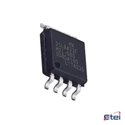
Hình ảnh chỉ để tham khảo
MCP2515-E/ST
+BOMIC CAN CONTROLLER W/SPI 20TSSOP
-
Nhà sản xuấtCông nghệ Microchip
-
Ông. Phần #MCP2515-E/ST
-
Bảng dữ liệu MCP2515-E/ST DataSheet
-
Gói TSSOP-20
-
Có sẵn3493
365 Đảm bảo chất lượng ngày
7*24 giờ dịch vụ quarantee
90-Bảo hành sau bán hàng ngày
Bảo hành sản phẩm chính xác
Thông số kỹ thuật
| thuộc tính | Giá trị |
| Package | Tube |
| ProductStatus | Active |
| Protocol | CANbus |
| Function | Controller |
| Interface | SPI |
| Standards | CAN 2.0 |
| Voltage-Supply | 2.7V ~ 5.5V |
| Current-Supply | 10mA |
| OperatingTemperature | -40°C ~ 125°C |
| Package/Case | 20-TSSOP (0.173, 4.40mm Width) |
Tổng quan
Description
Key features include support for the CAN 2.0B protocol, which allows for both standard and extended data and remote frames. The device can handle data rates up to 1 Mbps. It includes three transmit buffers, two receive buffers, and six filters with two masks, which help in efficient message handling and filtering.
The MCP2515-E/ST operates on a voltage range of 2.7V to 5.5V, making it suitable for a variety of systems. It also provides error detection and a low-power sleep mode. This chip is typically housed in an 18-pin SOIC package and is favored for its robust features and ease of integration.
Equivalent
1. NXP TJA1050 - A high-speed CAN transceiver used with a microcontroller.
2. TI SN65HVD230 - A CAN transceiver with similar functionalities.
3. Microchip MCP2561/2 - It is an advanced version of CAN transceivers suitable for various applications.
These products may not be direct drop-in replacements but serve similar functions in CAN communication systems. Ensure pin compatibility and feature matching when considering alternatives.
Features
Pinout
1. VDD (Pin 3): Power supply pin.
2. VSS (Pin 4): Ground reference pin.
3. CS (Pin 10): Chip Select input to activate the SPI interface.
4. SCK (Pin 11): Serial Clock input for the SPI interface.
5. SI (Pin 12): Serial Data Input for the SPI interface.
6. SO (Pin 13): Serial Data Output for the SPI interface.
7. RESET (Pin 14): Resets the device when driven low.
8. RX0BF (Pin 15) & RX1BF (Pin 16): Configurable buffer full pins for the receive buffers.
9. INT (Pin 17): Interrupt output pin.
10. CLKOUT (Pin 18): Clock Output which can be used for timing purposes.
11. TOSC1 (Pin 5) & TOSC2 (Pin 6): Oscillator pins for connecting an external crystal or ceramic resonator.
12. TXCAN (Pin 1): CAN transmit data output.
13. RXCAN (Pin 2): CAN receive data input.
It supports standard and extended data frame formats and is compliant with the CAN 2.0B protocol.