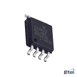
Hình ảnh chỉ để tham khảo
OP249GSZ
+BOM-
Nhà sản xuấtCông ty Analog Devices Inc.
-
Ông. Phần #OP249GSZ
-
Bảng dữ liệu OP249GSZ DataSheet
-
Có sẵn6061
365 Đảm bảo chất lượng ngày
7*24 giờ dịch vụ quarantee
90-Bảo hành sau bán hàng ngày
Bảo hành sản phẩm chính xác
Thông số kỹ thuật
| thuộc tính | Giá trị |
| Package | Tube |
| ProductStatus | Active |
| AmplifierType | J-FET |
| NumberofCircuits | 2 |
| SlewRate | 22V/µs |
| GainBandwidthProduct | 4.7 MHz |
| Current-InputBias | 30 pA |
| Voltage-InputOffset | 400 µV |
| Current-Supply | 5.6mA |
| Current-Output/Channel | 36 mA |
| Voltage-SupplySpan(Min) | 9 V |
| Voltage-SupplySpan(Max) | 36 V |
| OperatingTemperature | -40°C ~ 85°C |
| MountingType | Surface Mount |
| Package/Case | 8-SOIC (0.154, 3.90mm Width) |
Tổng quan
Description
Equivalent
Features
1. Quad Op-Amp Configuration: It includes four amplifiers in a single package, which is ideal for applications requiring multiple amplifiers.
2. Low Power Consumption: Designed for low power applications, making it suitable for battery-operated devices.
3. Wide Supply Voltage Range: It operates effectively over a wide range of supply voltages, enhancing its versatility.
4. High Slew Rate: Offers a fast response time, which is beneficial for high-speed applications.
5. Low Offset Voltage: Provides high precision with minimal voltage deviation, improving accuracy in analog signal processing.
6. CMOS Compatibility: Enables easy interfacing with other digital devices, adding to its flexibility.
7. Enhanced Stability: Features improved phase margin for stable operation in various configurations.
8. Temperature Range: Performs reliably over a broad temperature range, suitable for diverse environmental conditions.
These features make the OP249GSZ a versatile and reliable choice for various analog circuit applications, including signal conditioning, filtering, and amplification tasks.
Pinout
1. Pin 1: Output A - The output of the first operational amplifier.
2. Pin 2: Inverting Input A - The inverting input for the first operational amplifier.
3. Pin 3: Non-Inverting Input A - The non-inverting input for the first operational amplifier.
4. Pin 4: V- (or GND) - The negative power supply rail.
5. Pin 5: Non-Inverting Input B - The non-inverting input for the second operational amplifier.
6. Pin 6: Inverting Input B - The inverting input for the second operational amplifier.
7. Pin 7: Output B - The output of the second operational amplifier.
8. Pin 8: V+ - The positive power supply rail.
These amplifiers are used in various applications, including signal conditioning, filtering, and other analog signal processing tasks.