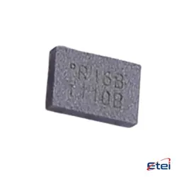
Hình ảnh chỉ để tham khảo
PC817X3NIPW
+BOMSHARP PHOTOCOUPLER
-
Nhà sản xuấtSHARP/Socle Technology
-
Ông. Phần #PC817X3NIPW
-
Có sẵn29229
365 Đảm bảo chất lượng ngày
7*24 giờ dịch vụ quarantee
90-Bảo hành sau bán hàng ngày
Bảo hành sản phẩm chính xác
Thông số kỹ thuật
| thuộc tính | Giá trị |
| Part Status | Active |
| Mounting Type | Surface Mount |
| Package / Case | 4-SMD, Gull Wing |
| Supplier Device Package | 4-SMD |
Tổng quan
Description
The PC817X3NIPW is an optocoupler or photocoupler, a component frequently used in electronic circuits for isolating different sections of a system. It consists of a light-emitting diode (LED) and a phototransistor housed together. The LED and phototransistor in the PC817X3NIPW are optically coupled but electrically isolated, allowing signals to pass between two isolated circuits using light.
This component is commonly used to protect sensitive parts of a circuit from voltage spikes or to interface different voltage levels. The PC817X3NIPW can be used in applications like switch mode power supplies, industrial automation, and microcontroller interfacing.
Key specifications include a CTR (Current Transfer Ratio) typically in the range of 50% to 600%, a maximum forward current of 50 mA for the LED, a maximum collector-emitter voltage of 80V, and an isolation voltage of 5000 Vrms. This makes it suitable for various applications requiring reliable electrical isolation and signal transmission.
This component is commonly used to protect sensitive parts of a circuit from voltage spikes or to interface different voltage levels. The PC817X3NIPW can be used in applications like switch mode power supplies, industrial automation, and microcontroller interfacing.
Key specifications include a CTR (Current Transfer Ratio) typically in the range of 50% to 600%, a maximum forward current of 50 mA for the LED, a maximum collector-emitter voltage of 80V, and an isolation voltage of 5000 Vrms. This makes it suitable for various applications requiring reliable electrical isolation and signal transmission.
Equivalent
The PC817X3NIPW is an optocoupler, and equivalent products include the LTV-817 series from Lite-On, the EL817 series from Everlight, the TLP785 series from Toshiba, and the SFH617A series from Vishay. These alternatives typically offer similar functions, including input-to-output isolation and signal transfer between circuits, but always verify specifications to ensure compatibility with your application.
Features
The PC817X3NIPW is a photocoupler or optocoupler, which is a component used to transfer electrical signals between two isolated circuits. Key features of the PC817X3NIPW include:
1. Isolation Voltage: It offers a high isolation voltage, typically around 5000 Vrms, which helps to protect and separate different parts of an electronic system.
2. Compact Package: Available in a small and efficient 4-pin DIP package, making it suitable for space-constrained applications.
3. High Reliability: Designed for reliability, making it suitable for use in a variety of applications, including industrial automation and consumer electronics.
4. Wide Operating Temperature: The device can operate over a broad temperature range, typically from -30°C to +100°C, making it versatile for different environments.
5. Input-Output Isolation: Provides reliable input-output isolation using an infrared LED and a phototransistor.
6. RoHS Compliant: The component is compliant with environmental and safety standards.
These features make the PC817X3NIPW suitable for use in applications such as signal isolation, power supply regulation, and data communication systems.
1. Isolation Voltage: It offers a high isolation voltage, typically around 5000 Vrms, which helps to protect and separate different parts of an electronic system.
2. Compact Package: Available in a small and efficient 4-pin DIP package, making it suitable for space-constrained applications.
3. High Reliability: Designed for reliability, making it suitable for use in a variety of applications, including industrial automation and consumer electronics.
4. Wide Operating Temperature: The device can operate over a broad temperature range, typically from -30°C to +100°C, making it versatile for different environments.
5. Input-Output Isolation: Provides reliable input-output isolation using an infrared LED and a phototransistor.
6. RoHS Compliant: The component is compliant with environmental and safety standards.
These features make the PC817X3NIPW suitable for use in applications such as signal isolation, power supply regulation, and data communication systems.
Pinout
The PC817X3NIPW is an optocoupler, also known as an opto-isolator, which typically has a 4-pin configuration. The pin count and function are as follows:
1. Pin 1 (Anode): This is the positive input pin for the internal LED. It is where the input signal is applied to activate the optocoupler.
2. Pin 2 (Cathode): This is the negative input pin for the internal LED. It completes the circuit for the LED when connected to ground or a lower potential compared to the anode.
3. Pin 3 (Emitter): This is one of the output pins connected to the phototransistor's emitter. It typically connects to ground or a low potential in the output circuit.
4. Pin 4 (Collector): This is the other output pin connected to the phototransistor's collector. It is where the output signal is taken, usually connected to a higher potential or the input of a subsequent stage in the circuit.
The optocoupler provides electrical isolation between the input and output, allowing signals to be transferred without a direct electrical connection.
1. Pin 1 (Anode): This is the positive input pin for the internal LED. It is where the input signal is applied to activate the optocoupler.
2. Pin 2 (Cathode): This is the negative input pin for the internal LED. It completes the circuit for the LED when connected to ground or a lower potential compared to the anode.
3. Pin 3 (Emitter): This is one of the output pins connected to the phototransistor's emitter. It typically connects to ground or a low potential in the output circuit.
4. Pin 4 (Collector): This is the other output pin connected to the phototransistor's collector. It is where the output signal is taken, usually connected to a higher potential or the input of a subsequent stage in the circuit.
The optocoupler provides electrical isolation between the input and output, allowing signals to be transferred without a direct electrical connection.
Application
The PC817X3NIPW is an optocoupler used primarily for isolating different circuit sections in electronic applications. Key application areas include:
1. Switching Power Supplies: Provides isolation between the control and high-voltage sections.
2. Microcontroller Interfacing: Facilitates safe communication between microcontrollers and high-voltage devices.
3. Industrial Automation: Used in PLCs and other automation equipment for signal isolation.
4. Consumer Electronics: Ensures safety and signal integrity in TVs, audio systems, and other devices.
5. Motor Control: Isolates control circuits from high-power motor drive circuits.
6. Signal Isolation: Prevents ground loops and protects against voltage spikes in sensitive electronic equipment.
These applications benefit from the optocoupler’s ability to provide electrical isolation and protect low-voltage circuits.
1. Switching Power Supplies: Provides isolation between the control and high-voltage sections.
2. Microcontroller Interfacing: Facilitates safe communication between microcontrollers and high-voltage devices.
3. Industrial Automation: Used in PLCs and other automation equipment for signal isolation.
4. Consumer Electronics: Ensures safety and signal integrity in TVs, audio systems, and other devices.
5. Motor Control: Isolates control circuits from high-power motor drive circuits.
6. Signal Isolation: Prevents ground loops and protects against voltage spikes in sensitive electronic equipment.
These applications benefit from the optocoupler’s ability to provide electrical isolation and protect low-voltage circuits.
Package
The PC817X3NIPW is an optocoupler with a through-hole package type. It typically comes in a 4-pin DIP (Dual Inline Package) form, which is standard for many optocouplers, allowing for easy integration onto printed circuit boards.