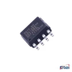
Hình ảnh chỉ để tham khảo
SN54LS138J
+BOM3-LINE TO 8-LINE DECODERS/DEMULT
-
Nhà sản xuấtTexas Dụng cụ
-
Ông. Phần #SN54LS138J
-
Bảng dữ liệu SN54LS138J DataSheet
-
Có sẵn9952
365 Đảm bảo chất lượng ngày
7*24 giờ dịch vụ quarantee
90-Bảo hành sau bán hàng ngày
Bảo hành sản phẩm chính xác
Thông số kỹ thuật
| thuộc tính | Giá trị |
| Series | 54LS |
| Part Status | Active |
| Type | Decoder/Demultiplexer |
| Circuit | 1 x 3:8 |
| Independent Circuits | 1 |
| Current - Output High, Low | 400µA, 4mA |
| Voltage Supply Source | Single Supply |
| Voltage - Supply | 4.5V ~ 5.5V |
| Operating Temperature | -55°C ~ 125°C |
| Mounting Type | Through Hole |
| Package / Case | 16-CDIP (0.300", 7.62mm) |
| Supplier Device Package | 16-CDIP |
Tổng quan
Description
The SN54LS138J offers high performance with fast switching speeds and low power consumption due to its TTL (Transistor-Transistor Logic) construction. It is housed in a J-lead ceramic dual in-line package, providing robust mechanical performance. This decoder is commonly used in applications requiring data routing, memory addressing, and as a demultiplexer for digital signal processing. Its reliability and versatility make it a staple in designing complex digital systems.
Equivalent
Features
1. 3-to-8 Line Decoder: Converts 3 binary inputs into 8 unique outputs.
2. Active Low Outputs: Outputs are active low, meaning they go low when selected.
3. Enable Inputs: Equipped with three enable inputs (two active low, one active high), allowing for easy cascading and expansion.
4. High-Speed Operation: Offers fast response times due to TTL technology.
5. Low Power Consumption: Designed for efficient power usage.
6. Wide Application Range: Suitable for memory address decoding, data routing, and demultiplexing applications.
7. Military-grade: SN54 series is designed to meet military specifications, offering better temperature and reliability metrics.
8. Package Type: Available in ceramic DIP packages, ensuring durability.
These features make the SN54LS138J suitable for a variety of digital applications where decoding or signal routing is required.
Pinout
Here is a brief outline of its pin configuration:
1. Inputs:
- A (Pin 1)
- B (Pin 2)
- C (Pin 3)
2. Enable Inputs:
- G1 (Pin 6) - Active-high enable
- G2A' (Pin 4) - Active-low enable
- G2B' (Pin 5) - Active-low enable
3. Outputs (Active-Low):
- Y0' (Pin 15)
- Y1' (Pin 14)
- Y2' (Pin 13)
- Y3' (Pin 12)
- Y4' (Pin 11)
- Y5' (Pin 10)
- Y6' (Pin 9)
- Y7' (Pin 7)
4. Power Supply:
- VCC (Pin 16) - Power supply
- GND (Pin 8) - Ground
This IC is used in applications that require selecting one line out of several based on binary input values, such as in memory address decoding.