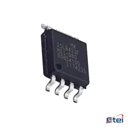
Hình ảnh chỉ để tham khảo
SN74HC273DWR
+BOMIC FF D-TYPE SNGL 8BIT 20SOIC
-
Nhà sản xuấtTexas Dụng cụ
-
Ông. Phần #SN74HC273DWR
-
Bảng dữ liệu SN74HC273DWR DataSheet
-
Có sẵn6184
365 Đảm bảo chất lượng ngày
7*24 giờ dịch vụ quarantee
90-Bảo hành sau bán hàng ngày
Bảo hành sản phẩm chính xác
Thông số kỹ thuật
| thuộc tính | Giá trị |
| Package | Tape & Reel (TR),Cut Tape (CT) |
| Series | 74HC |
| ProductStatus | Active |
| Function | Master Reset |
| Type | D-Type |
| OutputType | Non-Inverted |
| NumberofElements | 1 |
| NumberofBitsperElement | 8 |
| ClockFrequency | 60 MHz |
| MaxPropagationDelay@VMaxCL | 13ns @ 6V, 50pF |
| TriggerType | Positive Edge |
| Current-OutputHighLow | 5.2mA, 5.2mA |
| Voltage-Supply | 2V ~ 6V |
| Current-Quiescent(Iq) | 8 µA |
| InputCapacitance | 3 pF |
| OperatingTemperature | -40°C ~ 85°C (TA) |
| MountingType | Surface Mount |
| SupplierDevicePackage | 20-SOIC |
Tổng quan
Description
Data present at the D input is transferred to the Q output on the positive edge of the clock pulse, provided the clear (CLR) input is high. When CLR is low, the outputs are reset to a low logic level regardless of other inputs, allowing for asynchronous reset operations.
The SN74HC273DWR is commonly used in applications requiring data storage, data latching, and state retention, like registers and memory devices. It comes in a 20-pin SOIC (Small Outline Integrated Circuit) package, suitable for surface-mount technology, which supports efficient space usage on printed circuit boards. The device is known for its low power consumption and high-speed operation, compatible with TTL logic levels.
Equivalent
- Nexperia 74HC273D
- ON Semiconductor MC74HC273ADWG
- Fairchild/ON Semiconductor 74HC273
These chips generally offer similar functionality and electrical characteristics, but always verify the datasheets for exact specifications and compatibility.
Features
1. High-Speed Performance: It offers fast operation with a typical propagation delay.
2. Wide Supply Voltage Range: Operates from 2V to 6V, ensuring compatibility with both 3.3V and 5V systems.
3. Low Power Consumption: Features low static power dissipation.
4. High Noise Immunity: Provides robust performance in noisy environments.
5. Direct Clear Input: Allows asynchronous clearing of all outputs to a low state.
6. Latch-Up Performance: Withstands up to 100 mA per JESD 17 standard.
7. Input/Output Compatibility: TTL-compatible inputs for both current and voltage levels.
8. Package: Available in a small outline package, suitable for space-constrained applications.
These features make the SN74HC273DWR suitable for applications requiring reliable data storage and transfer functions, such as registers and control circuits in digital systems.
Pinout
The device comes in a 20-pin SOIC (Small Outline Integrated Circuit) package. Here's a brief overview of its pin functions:
- Pins 1-8, 10-17 (Q0-Q7): These are the flip-flop outputs corresponding to the eight data bits.
- Pin 9 (MR): The master reset pin. It clears all flip-flops when held low.
- Pin 19 (CP): This is the clock input. A rising edge on this pin transfers the data from the D inputs to the Q outputs.
- Pins 3-6, 11-14 (D0-D7): These are the data input pins for the eight flip-flops.
- Pin 20 (VCC): This is the supply voltage pin.
- Pin 10 (GND): The ground pin for the device.
The SN74HC273DWR is widely used for its reliability and efficiency in applications requiring data storage and transfer.