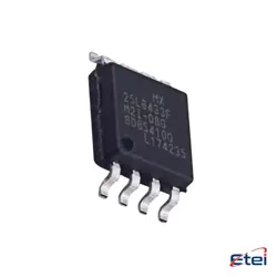
Hình ảnh chỉ để tham khảo
SN74LV74APWR
+BOMIC FF D-TYPE DUAL 1BIT 14TSSOP
-
Nhà sản xuấtTexas Dụng cụ
-
Ông. Phần #SN74LV74APWR
-
Bảng dữ liệu SN74LV74APWR DataSheet
-
Gói TSSOP14
-
Có sẵn3881
365 Đảm bảo chất lượng ngày
7*24 giờ dịch vụ quarantee
90-Bảo hành sau bán hàng ngày
Bảo hành sản phẩm chính xác
Thông số kỹ thuật
| thuộc tính | Giá trị |
| Package | Tape & Reel (TR),Cut Tape (CT) |
| Series | 74LV |
| ProductStatus | Active |
| Function | Set(Preset) and Reset |
| Type | D-Type |
| OutputType | Complementary |
| NumberofElements | 2 |
| NumberofBitsperElement | 1 |
| ClockFrequency | 140 MHz |
| MaxPropagationDelay@VMaxCL | 9.3ns @ 5V, 50pF |
| TriggerType | Positive Edge |
| Current-OutputHighLow | 12mA, 12mA |
| Voltage-Supply | 2V ~ 5.5V |
| Current-Quiescent(Iq) | 20 µA |
| InputCapacitance | 2 pF |
| OperatingTemperature | -40°C ~ 125°C (TA) |
| MountingType | Surface Mount |
| SupplierDevicePackage | 14-TSSOP |
Tổng quan
Description
Operating from a voltage range of 2V to 5.5V, the SN74LV74APWR offers broad compatibility with various logic levels. It is characterized by low power consumption and high-speed operation, making it suitable for a wide range of applications including data storage, counters, and shift registers. The 'APWR' suffix indicates the package type, which is TSSOP (Thin Shrink Small Outline Package), featuring a compact footprint ideal for high-density circuit boards. Additionally, it is compliant with industry standards for RoHS and lead-free specifications, ensuring environmental safety.
Equivalent
1. Nexperia 74LVC74
2. ON Semiconductor MC74HC74A
3. Fairchild Semiconductor 74HC74
4. Microchip Technology 74ACT74
5. STMicroelectronics M74HC74
These ICs provide similar functionality with differences in voltage levels or performance characteristics, so ensure compatibility with your specific application requirements.
Features
Pinout
1. 1CLR (Pin 1): Asynchronous clear for the first flip-flop (active low).
2. 1D (Pin 2): Data input for the first flip-flop.
3. 1CLK (Pin 3): Clock input for the first flip-flop.
4. 1PRE (Pin 4): Asynchronous preset for the first flip-flop (active low).
5. 1Q (Pin 5): Non-inverted output for the first flip-flop.
6. 1Q̅ (Pin 6): Inverted output for the first flip-flop.
7. GND (Pin 7): Ground.
8. 2Q̅ (Pin 8): Inverted output for the second flip-flop.
9. 2Q (Pin 9): Non-inverted output for the second flip-flop.
10. 2PRE (Pin 10): Asynchronous preset for the second flip-flop (active low).
11. 2CLK (Pin 11): Clock input for the second flip-flop.
12. 2D (Pin 12): Data input for the second flip-flop.
13. 2CLR (Pin 13): Asynchronous clear for the second flip-flop (active low).
14. VCC (Pin 14): Supply voltage.
These flip-flops are commonly used for data storage and transfer applications.
Manufacturer
Application
1. Data Storage and Transfer: It captures, stores, and transfers data reliably in digital circuits.
2. Frequency Division: Used in frequency division applications to divide clock signals.
3. Counters and Registers: Acts as a fundamental building block for designing counters and shift registers.
4. State Machines: Utilized in the implementation of finite state machines for control applications.
5. Synchronization: Helps synchronize asynchronous signals in digital systems.
The device’s low-voltage operation and high-speed performance make it suitable for various consumer electronics, communication equipment, and automotive applications.