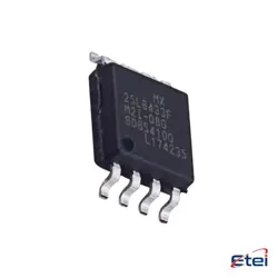
Hình ảnh chỉ để tham khảo
STD60NF04LT
+BOMMOSFETs
-
Nhà sản xuấtSTMicroelectronics
-
Ông. Phần #STD60NF04LT
-
Có sẵn24381
365 Đảm bảo chất lượng ngày
7*24 giờ dịch vụ quarantee
90-Bảo hành sau bán hàng ngày
Bảo hành sản phẩm chính xác
Thông số kỹ thuật
| thuộc tính | Giá trị |
Tổng quan
Description
The STD60NF04LT is an N-channel MOSFET (Metal-Oxide-Semiconductor Field-Effect Transistor) designed for efficient switching and amplification in electronic circuits. It is part of the STMicroelectronics' STPOWER™ series. This MOSFET is built using advanced technologies to deliver low on-state resistance, which ensures high efficiency and low power loss during operation. The STD60NF04LT is ideal for applications involving low voltage and high-speed switching operations.
Key specifications include a maximum drain-source voltage (V_DS) of 40V and a continuous drain current (I_D) of 60A. It features fast switching capabilities and robust thermal performance, making it suitable for power management applications like DC-DC converters, motor drivers, and battery management systems.
The device is typically available in DPAK (TO-252) packaging, which provides a compact footprint and efficient thermal dissipation. With its reliable performance and energy-efficient operation, the STD60NF04LT is a versatile component in both consumer and industrial electronic designs.
Key specifications include a maximum drain-source voltage (V_DS) of 40V and a continuous drain current (I_D) of 60A. It features fast switching capabilities and robust thermal performance, making it suitable for power management applications like DC-DC converters, motor drivers, and battery management systems.
The device is typically available in DPAK (TO-252) packaging, which provides a compact footprint and efficient thermal dissipation. With its reliable performance and energy-efficient operation, the STD60NF04LT is a versatile component in both consumer and industrial electronic designs.
Equivalent
Equivalent products for the STD60NF04LT MOSFET include:
1. IRFZ44N - A popular N-channel MOSFET with similar voltage and current ratings.
2. FQP30N06L - Another N-channel MOSFET with comparable characteristics.
3. STP55NF06 - A similar STMicroelectronics MOSFET with slightly different specs.
4. RFP70N06 - Fairchild's equivalent with similar performance.
Always check the datasheets to ensure compatibility with your specific application.
1. IRFZ44N - A popular N-channel MOSFET with similar voltage and current ratings.
2. FQP30N06L - Another N-channel MOSFET with comparable characteristics.
3. STP55NF06 - A similar STMicroelectronics MOSFET with slightly different specs.
4. RFP70N06 - Fairchild's equivalent with similar performance.
Always check the datasheets to ensure compatibility with your specific application.
Features
The STD60NF04LT is an N-channel MOSFET with several notable features. It is designed for use in applications requiring efficient high-speed switching. Key features include:
1. Voltage and Current Ratings: It has a drain-source voltage (V_DS) of 40V and can handle a continuous drain current (I_D) of up to 60A.
2. Low On-Resistance: The MOSFET features a low on-state resistance (R_DS(on)) of 0.016Ω, improving conduction efficiency and reducing power loss.
3. Gate Threshold Voltage: A gate threshold voltage (V_GS(th)) typically around 2-4V allows for compatibility with low-voltage drive signals.
4. Fast Switching: The device supports fast switching speeds, making it suitable for high-frequency applications.
5. Package Type: It is offered in a TO-252 (DPAK) package, which is surface-mountable, facilitating compact design layouts.
These specifications make the STD60NF04LT suitable for applications such as power management, motor control, and DC-DC converters, where efficient power switching is essential.
1. Voltage and Current Ratings: It has a drain-source voltage (V_DS) of 40V and can handle a continuous drain current (I_D) of up to 60A.
2. Low On-Resistance: The MOSFET features a low on-state resistance (R_DS(on)) of 0.016Ω, improving conduction efficiency and reducing power loss.
3. Gate Threshold Voltage: A gate threshold voltage (V_GS(th)) typically around 2-4V allows for compatibility with low-voltage drive signals.
4. Fast Switching: The device supports fast switching speeds, making it suitable for high-frequency applications.
5. Package Type: It is offered in a TO-252 (DPAK) package, which is surface-mountable, facilitating compact design layouts.
These specifications make the STD60NF04LT suitable for applications such as power management, motor control, and DC-DC converters, where efficient power switching is essential.
Pinout
The STD60NF04LT is an N-channel MOSFET designed for use in various electronic applications. It typically comes in a TO-252 package, also known as DPAK, which has three pins. The pin configuration and functions are as follows:
1. Gate (G): This pin is responsible for controlling the MOSFET. Applying a voltage to the gate allows current to flow from the drain to the source.
2. Drain (D): The drain is the terminal through which the main current flows into the MOSFET when it is in the "on" state. It is usually connected to the load.
3. Source (S): This terminal is the return path for the current flowing through the MOSFET. It is typically connected to ground or a lower potential in the circuit.
The MOSFET is used for switching and amplifying signals in various power management applications. Its main features include low on-resistance, fast switching speed, and high current handling capability, making it suitable for use in power supply circuits, motor control, and other high-power applications.
1. Gate (G): This pin is responsible for controlling the MOSFET. Applying a voltage to the gate allows current to flow from the drain to the source.
2. Drain (D): The drain is the terminal through which the main current flows into the MOSFET when it is in the "on" state. It is usually connected to the load.
3. Source (S): This terminal is the return path for the current flowing through the MOSFET. It is typically connected to ground or a lower potential in the circuit.
The MOSFET is used for switching and amplifying signals in various power management applications. Its main features include low on-resistance, fast switching speed, and high current handling capability, making it suitable for use in power supply circuits, motor control, and other high-power applications.
Manufacturer
The STD60NF04LT is manufactured by STMicroelectronics. STMicroelectronics is a global semiconductor company that designs, develops, manufactures, and markets a wide range of semiconductor products and solutions. The company serves a variety of markets, including automotive, industrial, personal electronics, computer, and communication equipment. With a strong focus on innovation, STMicroelectronics produces both standard and custom devices and is known for its expertise in microcontrollers, power management, sensors, and connectivity solutions.
Application
The STD60NF04LT is an N-channel MOSFET commonly used in various electronic applications. Its application areas include:
1. Power Management: Utilized in power supply circuits and voltage regulation due to its high efficiency and fast switching capabilities.
2. Motor Control: Employed in driving motors for applications such as fans, pumps, and other machinery.
3. Automotive Systems: Used in vehicle electronics for controlling power distribution and managing loads.
4. Switching Circuits: Suitable for use in DC-DC converters and inverters.
5. Consumer Electronics: Applied in devices such as TVs, audio equipment, and other household appliances for efficient power handling.
These applications benefit from the MOSFET's low on-resistance and high current handling capabilities.
1. Power Management: Utilized in power supply circuits and voltage regulation due to its high efficiency and fast switching capabilities.
2. Motor Control: Employed in driving motors for applications such as fans, pumps, and other machinery.
3. Automotive Systems: Used in vehicle electronics for controlling power distribution and managing loads.
4. Switching Circuits: Suitable for use in DC-DC converters and inverters.
5. Consumer Electronics: Applied in devices such as TVs, audio equipment, and other household appliances for efficient power handling.
These applications benefit from the MOSFET's low on-resistance and high current handling capabilities.
Package
The STD60NF04LT is a MOSFET that comes in a DPAK (TO-252) package type. This package is commonly used for surface-mount applications, providing efficient heat dissipation and compact design suitable for high-density circuit boards.