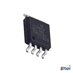
Hình ảnh chỉ để tham khảo
UCC5310MCDWVR
+BOMDGTL ISO 3KV 1CH GATE DVR 8SOIC
-
Nhà sản xuấtTexas Dụng cụ
-
Ông. Phần #UCC5310MCDWVR
-
Có sẵn3068
365 Đảm bảo chất lượng ngày
7*24 giờ dịch vụ quarantee
90-Bảo hành sau bán hàng ngày
Bảo hành sản phẩm chính xác
Thông số kỹ thuật
| thuộc tính | Giá trị |
| Part Status | Active |
| Technology | Capacitive Coupling |
| Number of Channels | 1 |
| Voltage - Isolation | 3000Vrms |
| Common Mode Transient Immunity (Min) | 100kV/µs |
| Propagation Delay tp LH / tp HL (Max) | 75ns, 75ns |
| Pulse Width Distortion (Max) | 20ns |
| Rise / Fall Time (Typ) | 12ns, 10ns |
| Current - Output High, Low | 2.4A, 1.1A |
| Current - Peak Output | 4.3A |
| Voltage - Output Supply | 13.2V ~ 33V |
| Operating Temperature | -40°C ~ 125°C |
| Mounting Type | Surface Mount |
| Package / Case | 8-SOIC (0.295", 7.50mm Width) |
| Supplier Device Package | 8-SOIC |
| Approval Agency | CQC, UR, VDE |
| Base Product Number | UCC5310 |
Tổng quan
Description
The UCC5310MCDWVR is an isolated gate driver from Texas Instruments, designed to drive IGBTs, MOSFETs, and SiC MOSFETs. It features a reinforced isolation barrier, offering up to 3.75 kVrms of isolation, which is critical for high-voltage applications. This device provides efficient power conversion and ensures safety in designs by preventing high-voltage spikes from affecting low-voltage control systems.
Key features include fast switching capability, minimizing switching losses, and a split output for separate sourcing and sinking currents, enhancing control over device turn-on and turn-off. The UCC5310MCDWVR supports various protection features, such as UVLO (Under-Voltage Lockout) to ensure reliable operation even under low voltage conditions. It is suitable for applications like solar inverters, motor drives, and industrial power supplies.
The device is compact, typically available in a small SOIC-8 package, making it easy to integrate into space-constrained designs. Its reliability, efficiency, and robust isolation make it a popular choice for engineers working with high-power electronics.
Key features include fast switching capability, minimizing switching losses, and a split output for separate sourcing and sinking currents, enhancing control over device turn-on and turn-off. The UCC5310MCDWVR supports various protection features, such as UVLO (Under-Voltage Lockout) to ensure reliable operation even under low voltage conditions. It is suitable for applications like solar inverters, motor drives, and industrial power supplies.
The device is compact, typically available in a small SOIC-8 package, making it easy to integrate into space-constrained designs. Its reliability, efficiency, and robust isolation make it a popular choice for engineers working with high-power electronics.
Equivalent
The UCC5310MCDWVR is a single-channel isolated gate driver from Texas Instruments. Equivalent products from other manufacturers include the ADuM4121 from Analog Devices, 1EDB7275F from Infineon Technologies, and the Si82394 from Silicon Labs. These alternatives generally offer similar isolation voltage ratings and drive capabilities, but specific features may vary, so it is important to review their datasheets for detailed specifications and ensure compatibility with your application requirements.
Features
The UCC5310MCDWVR is a high-performance isolated gate driver designed by Texas Instruments. It features a robust isolation capability of up to 3 kV RMS, making it suitable for applications requiring reliable galvanic isolation. The driver is optimized for driving both IGBTs and SiC MOSFETs, supporting high-speed switching with a propagation delay of typically 100 ns. It provides a peak source and sink current of 2.5 A and 5 A, respectively, facilitating efficient and effective switching of power devices.
The device operates over a wide temperature range from -40°C to 125°C, ensuring performance stability in various environmental conditions. Its common-mode transient immunity (CMTI) is greater than 100 V/ns, which enhances the driver's robustness against fast transients. The UCC5310MCDWVR is housed in a compact SOIC-8 package with an industry-standard pinout, simplifying integration into existing designs. Additional features include under-voltage lockout (UVLO) protection on both the primary and secondary sides, which ensures the driver's safe operation and reliability in power management applications.
The device operates over a wide temperature range from -40°C to 125°C, ensuring performance stability in various environmental conditions. Its common-mode transient immunity (CMTI) is greater than 100 V/ns, which enhances the driver's robustness against fast transients. The UCC5310MCDWVR is housed in a compact SOIC-8 package with an industry-standard pinout, simplifying integration into existing designs. Additional features include under-voltage lockout (UVLO) protection on both the primary and secondary sides, which ensures the driver's safe operation and reliability in power management applications.
Pinout
The UCC5310MCDWVR is a single-channel isolated gate driver manufactured by Texas Instruments. It typically comes in an 8-pin SOIC (Small Outline Integrated Circuit) package. The key function of this device is to provide galvanic isolation and drive power MOSFETs and IGBTs in various applications, such as motor drives and industrial inverters.
The pin configuration generally includes:
1. VDD1: Supply voltage for the input side.
2. IN: Input signal for controlling the gate driver.
3. GND1: Ground for the input side.
4. NC: No Connection (can vary based on specific package configurations).
5. VDD2: Supply voltage for the output side.
6. OUT: Output signal for driving the gate of a power transistor.
7. GND2: Ground for the output side.
8. EN: Enable pin (used to enable or disable the output).
Please refer to the official datasheet for the most accurate and detailed information regarding pin configuration and function.
The pin configuration generally includes:
1. VDD1: Supply voltage for the input side.
2. IN: Input signal for controlling the gate driver.
3. GND1: Ground for the input side.
4. NC: No Connection (can vary based on specific package configurations).
5. VDD2: Supply voltage for the output side.
6. OUT: Output signal for driving the gate of a power transistor.
7. GND2: Ground for the output side.
8. EN: Enable pin (used to enable or disable the output).
Please refer to the official datasheet for the most accurate and detailed information regarding pin configuration and function.
Manufacturer
The UCC5310MCDWVR is manufactured by Texas Instruments. Texas Instruments (TI) is a global company based in Dallas, Texas, known for designing and manufacturing semiconductors and various integrated circuits. TI's products are used in a broad range of electronic applications across numerous industries, including consumer electronics, automotive, industrial, communications equipment, and enterprise systems. The company is particularly well-known for its analog chips and embedded processors, and its products often serve as critical components in devices that provide sensing, processing, power management, and signal conversion.
Application
The UCC5310MCDWVR is an isolated gate driver IC used primarily in power electronics applications. Its main application areas include:
1. Industrial Motor Drives: Enhances efficiency and control in motor systems.
2. Renewable Energy Systems: Used in inverters for solar panels and wind turbines.
3. Power Supply Units: Provides isolation and drive capabilities in switched-mode power supplies.
4. Electric Vehicles (EVs): Integral in EV powertrain, ensuring efficient power conversion.
5. Uninterruptible Power Supplies (UPS): Improves reliability and efficiency of backup power systems.
6. HVAC Systems: Contributes to energy-efficient motor control for heating, ventilation, and air conditioning systems.
These applications benefit from the device's ability to provide high-efficiency, reliable isolation and switching capabilities.
1. Industrial Motor Drives: Enhances efficiency and control in motor systems.
2. Renewable Energy Systems: Used in inverters for solar panels and wind turbines.
3. Power Supply Units: Provides isolation and drive capabilities in switched-mode power supplies.
4. Electric Vehicles (EVs): Integral in EV powertrain, ensuring efficient power conversion.
5. Uninterruptible Power Supplies (UPS): Improves reliability and efficiency of backup power systems.
6. HVAC Systems: Contributes to energy-efficient motor control for heating, ventilation, and air conditioning systems.
These applications benefit from the device's ability to provide high-efficiency, reliable isolation and switching capabilities.
Package
The UCC5310MCDWVR is packaged in a SOIC (Small Outline Integrated Circuit) format, specifically an 8-pin wide-body SOIC. This package type is known for offering good thermal performance and ease of handling in surface-mount technology applications.